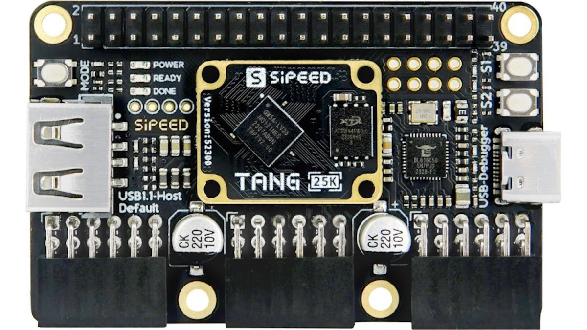
Sipeed Tang Nano 20K FPGA board
Sipeed in China produces a range of little low-cost DIL modules using Gowin FPGAs. They are available via AliExpress. The 20K costs about £26 and contains a GW2AR-18 QN88 device:
https://wiki.sipeed.com/hardware/en/tang/tang-nano-20k/nano-20k.html
I ordered one about a week ago and it was delivered by Evri this morning. I connected it to my laptop using the supplied USB cable and the orange LEDs lit up in sequence continuously indicating that it was working.
I downloaded a Verilog file which simply blinked one LED at 1 Hz, the associated physical constraints file and the timing constraints file.
The Verilog is compiled to produce a netlist that is placed and routed, generating a bitstream that is downloaded into the chip.
Here's the Verilog file (Blink_LED.v):
module led (
input sys_clk,
input sys_rst_n, // reset input
output reg led // LED
);
reg [23:0] counter;
always @(posedge sys_clk or negedge sys_rst_n) begin // Counter block
if (!sys_rst_n)
counter <= 24'd0;
else if (counter < 24'd1349_9999) // 0.5s delay
counter <= counter + 1'b1;
else
counter <= 24'd0;
end
always @(posedge sys_clk or negedge sys_rst_n) begin // Toggle LED
if (!sys_rst_n)
led <= 1'b1;
else if (counter == 24'd1349_9999) // 0.5s delay
led <= ~led; // ToggleLED
end
endmodule
Physical constraints file ( Blink_LED.cst):
IO_LOC "led" 15;
IO_PORT "led" IO_TYPE=LVCMOS33;
IO_LOC "sys_clk" 4;
IO_PORT "sys_clk" PULL_MODE=UP IO_TYPE=LVCMOS33;
Timing constraints file ( Blink_LED.sdc):
create_clock -name clk_27M -period 37.037 -waveform {0 18.518} [get_ports {sys_clk}]
The EDA tools can accept both Verilog and VHDL. Verilog is based on C and VHDL (Very High Speed Integrated Circuit (VHSIC) Hardware Description Language) is based on Ada. Verilog is popular in the USA and VHDL is used more in Europe.
I created a project folder called Blink_LED, ran the Gowin EDA tools, clicked on New Project, called it Blink_LED, and the project was created. I copied the three downloaded files into the src (source) folder. A right click on the project enabled me to add the files to the project. They automagically show up in the correct location in the Design window, according to the file extensions: v, cst and sdc. Select Process.
Click on Run All - the two curved arrows at the right of the symbols at the top of the EDA window. You should see ticks against Synthesis and Place & Route in the Design Summary.
Connect your Tang Nano 20K target board to your PC via USB and double click on Programmer. Save the Cable Setting.
Select SRAM Program.
Click on Program/Configure (rightmost button to the left of "USB Cable Setting". The bitstream is downloaded to the chip and you should see one of the LEDs flashing. The configuration is only in SRAM and will disappear when power is removed,. The module will then revert to the configuration saved in the external flash memory.
Here's the Verilog converted to VHDL by ChatGPT:
library IEEE;
use IEEE.STD_LOGIC_1164.ALL;
use IEEE.STD_LOGIC_ARITH.ALL;
use IEEE.STD_LOGIC_UNSIGNED.ALL;
entity led is
Port (
sys_clk : in STD_LOGIC;
sys_rst_n : in STD_LOGIC; -- reset input
led : out STD_LOGIC -- LED
);
end led;
architecture Behavioral of led is
signal counter : STD_LOGIC_VECTOR(23 downto 0) := (others => '0'); -- Define a signal to count
signal led_reg : STD_LOGIC := '1'; -- Register for LED
begin
process(sys_clk, sys_rst_n)
begin
if sys_rst_n = '0' then
counter <= (others => '0');
elsif rising_edge(sys_clk) then
if counter < "110011011111011111111111" then -- 0.5s delay
counter <= counter + 1;
else
counter <= (others => '0');
end if;
end if;
end process;
process(sys_clk, sys_rst_n)
begin
if sys_rst_n = '0' then
led_reg <= '1';
elsif rising_edge(sys_clk) then
if counter = "110011011111011111111111" then -- 0.5s delay
led_reg <= not led_reg; -- Toggle LED
end if;
end if;
end process;
led <= led_reg;
end Behavioral;
ChatGPT kindly provided some notes:
Libraries and packages are included at the beginning.
The entity led is defined with ports sys_clk, sys_rst_n, and led.
The architecture Behavioral contains the signals counter and led_reg.
Two processes handle the counter and LED toggling, similar to the Verilog code's always blocks.
The counter process increments the counter or resets it based on the clock and reset signals.
The led_reg process toggles the LED when the counter reaches the specified value.
The output led is assigned the value of led_reg.
Comments in VHDL are preceded by two dashes.


Comments
Post a Comment